


I/O simulators for telemetry modules
For some models of telemetry modules, the I/O simulators have been developed. They allow you to easily test the functionality of the module, the correctness of configuration settings, as well
as the actual operation of the user’s application program. Here we present available models of simulators.
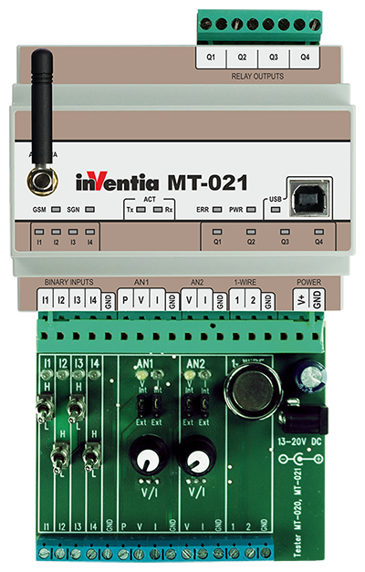 MT-IS-02x – input simulator for MT-020, MT-021 modules
The MT-IS-02x simulator works with MT-020 and MT-021 modules and enables:
- feeding the binary inputs I1 – I4 by voltage 0 V (corresponding to the logic L) or +12 V (corresponding to the logic H, signaled by lighting the green LED), using switches;
- supplying the external voltage to I1 – I4 inputs;
- feeding the analog input AN1 by the voltage in the range of 0 – 10 V (signaled by the brightness of the white LED), or by the current in the range of 4 – 20 mA (signaled by the brightness of the yellow LED), using a potentiometer;
- connecting an external PT100 sensor or an external voltage converter or an external current converter to the analog input AN1;
- feeding the analog input AN2 by the voltage in the range of 0 – 10 V (signaled by the brightness of the white LED), or by the current in the range of 4 – 20 mA (signaled by the brightness of the yellow LED), using a potentiometer;
- connecting an external NTC sensor or an external voltage converter or an external current converter to the analog input AN2;
- attaching the Dallas pellet to the No. 1 1-Wire input;
- the connection of external elements to both 1-Wire inputs.
The simulator should be powered by an external 13 – 20 VDC power supply (typically 15 VDC).
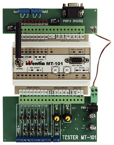 MT-IOS-101 – simulator for MT-101 and EX-101 modules
The MT-IOS-101 simulator is designed to work with MT-101 and EX-101 modules. This model consists of two boards that are plugged into the module terminal block sockets and enables:
- feeding the binary/counter inputs I1 – I8 by voltage 0 V (corresponding to the logic L) or +12 V (corresponding to the logic H, signaled by lighting the green LED), using switches;
- supplying the external voltage to I1 – I8 inputs;
- feeding the analog input I1 and I2 by the current in the range of 4 – 20 mA (signaled by the brightness of the yellow LED), using a potentiometer;
- supplying the analog input I1 from an external current source;
- connection to binary outputs Q1 and Q2 buffered with relays,
- resistive load up to 250 VAC / 2 A or inductive load up to 125 VAC / 0.5 A;
- monitoring of logic states of Q1 – Q8 outputs signaled by the lighting of red LEDs;
- the connection of the RS-232 serial port,
- simulation of the battery’s connection to the UPS input
The simulator should be powered by an external 13 – 30 VDC power supply (typically 15 VDC).
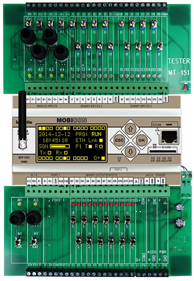 MT-IOS-151 – simulator for MT-151 and MT-151 v2 modules
The MT-IOS-151 simulator works with MT-151 LED, MT-151 HMI, MT-151 LED v2 and MT-151 HMI v2 modules. This model consists of two boards that are plugged into the module terminal block
sockets and enables:
- feeding the binary/counter inputs I1 – I16 by voltage 0 V (corresponding to the logic L) or +12 V (corresponding to the logic H, signaled by lighting the green LED), using switches;
- supplying the external voltage to I1 – I16 inputs;
- feeding the analog inputs I1 – I4 by the current in the range of 4 – 20 mA (signaled by the brightness of the yellow LED), using a potentiometer;
- supplying the analog input I1 – I4 from an external current source;
- connection to binary outputs Q1 and Q2 buffered with relays,
- feeding the analog voltage inputs I1 – I4 by the voltage in the range of 0 – 10 V (signaled by the brightness of the white LED);
- the connection of power outputs to the COM2 and Q+ terminals;
- monitoring of logic states of the Q1 – Q12 outputs signaled by the lighting of red LEDs;
- attaching external loads to the Q1 – Q12 outputs;
- the connection of opto-isolated Port 1 (RS-232/485);
- the connection of Port 2 (RS-232);
- the connection of an external 12V battery
The simulator should be powered by an external 13 – 30 VDC power supply (typically 15 VDC).
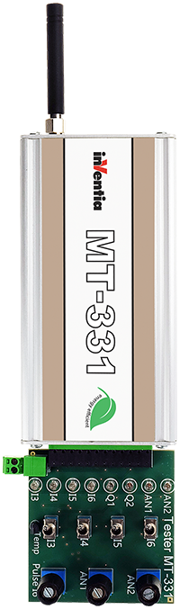 MT-IOS-331 – simulator for MT-331 module
The MT-IOS-331 simulator works with MT-331 module and enables:
- feeding the analog voltage inputs AN1 and AN2 by the voltage in the range of 0 – 10 V (signaled by the brightness of the white LED), using a potentiometer;
- ground shorting of binary inputs I3, I4, I5, I6, which is signaled by lighting green LEDs;
- shorting to the ground of input I6 by means of a rotary encoder, which enables the delivery of a series of pulses and is signaled by lighting the green LED;
- signaling binary outputs states Q1 and Q2 using red LEDs;
- measuring the ambient temperature with a sensor connected to the 1-Wire input;
The simulator can be powered by an external 9 – 30 VDC power supply or from the internal battery of MT-331 module.