
Inventia modules in EPLAN – less time spent on documentation, more time for the project
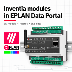
Inventia modules in EPLAN - less time spent on documentation, more time for the project
When designing a control cabinet, selecting the equipment is only part of the job. You also need to prepare schematics, lay out the equipment, describe the connections and draw up a bill of materials. If the data for a selected module is missing from the library, the designer must create a representation of it themselves and fill in the parameters. This takes time, especially when using a piece of equipment for the first time.
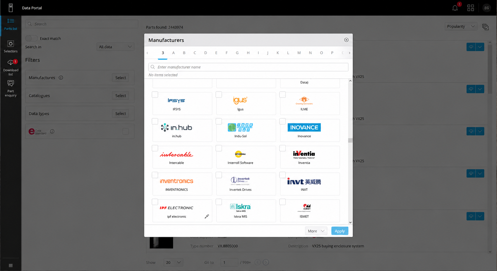
To make this work easier, we have made the Inventia module library on the EPLAN Data Portal available. It contains macros, 3D models and item data compliant with the EPLAN Data Standard. These can be used in EPLAN platform solutions according to the task at hand – from creating electrical schematics to designing cabinet layouts.
Find out:
-
Which Inventia devices can you find on the EPLAN Data Portal?
-
How can you use ready-made data in your design work?
-
How do 3D models make it easier to plan cabinet layouts?
-
How can you minimise manual data entry and the risk of errors?
-
How does using the Inventia library help reduce the cost of preparing documentation?
-
How can you improve collaboration between the designer and the contractor?
-
Why is the library also useful for future projects?
-
Where can you find the Inventia library and get started?
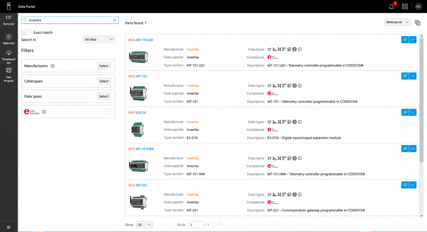
Which devices can you find in the library?
The data provided includes:
the MT-121 controller,
the MT-151 HMI and MT-151 LED controllers,
the MT-156 controller,
the MT-221 controller,
the EX-A41 and EX-D16 expanders.
The EPLAN Data Portal is where you download the data. How you use it further depends on the programme’s functions: macros support the creation of schematics, 3D models are used for layout planning, and item data help you prepare lists of the devices used.
Faster integration of a module into a project
The first benefit is simple: the designer does not have to create a component from scratch.
Ready-made macros reduce the need for manual drawing and preparing your own device representation. Product data allows you to use the manufacturer’s information rather than re-entering it into the project database. As a result, once a module has been selected, you can move on more quickly to designing its connections and functions within the installation.
This is important for both single control cabinets and larger projects. If the project involves a dozen or so pumping stations or dispersed measurement points, the prepared component can be reused in subsequent documentation, adapting the layout to the equipment at each site.
Easier planning of space within the cabinet
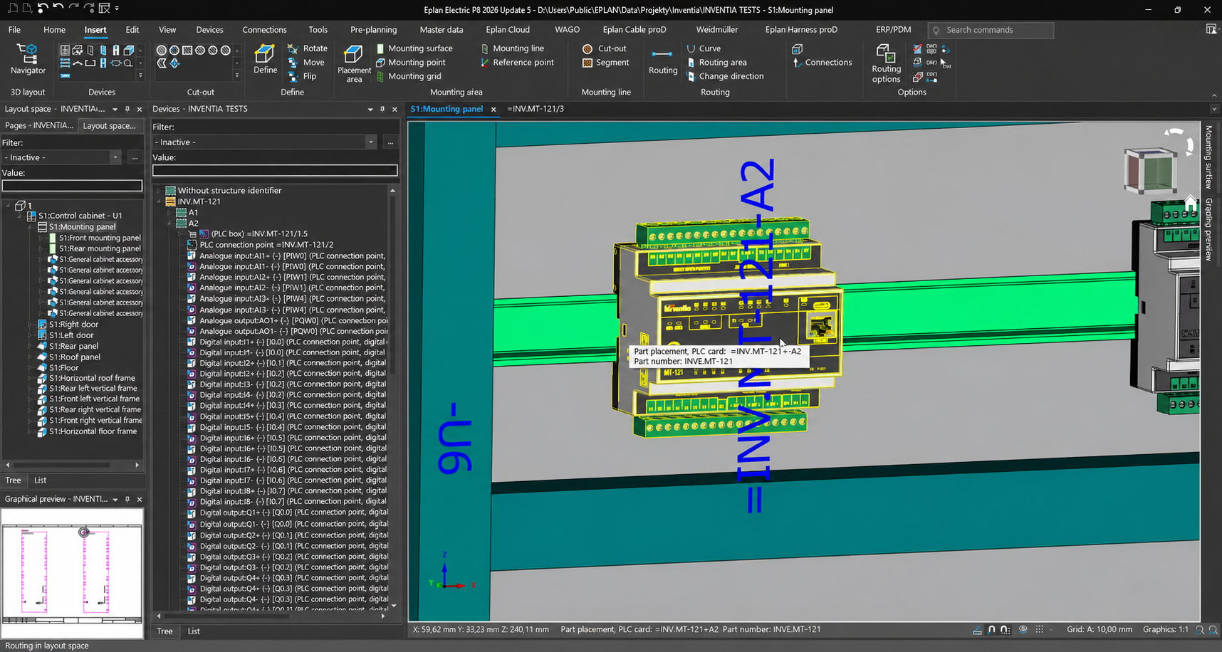
A device will always fit on an electrical diagram. Within the cabinet, however, its actual dimensions, neighbouring equipment, cable trays and the space required for connecting cables must be taken into account.
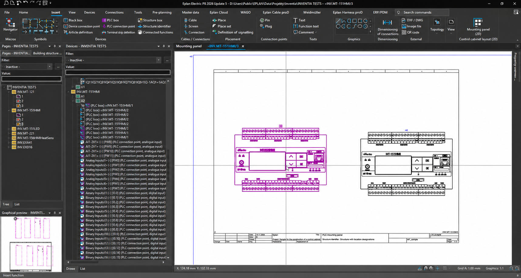
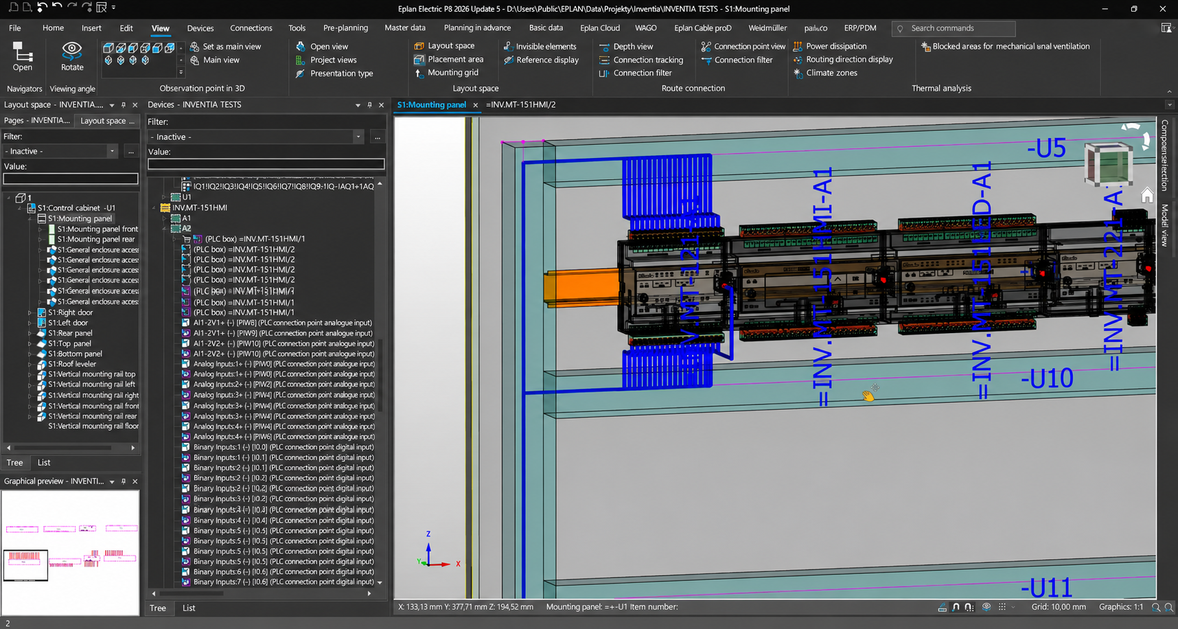
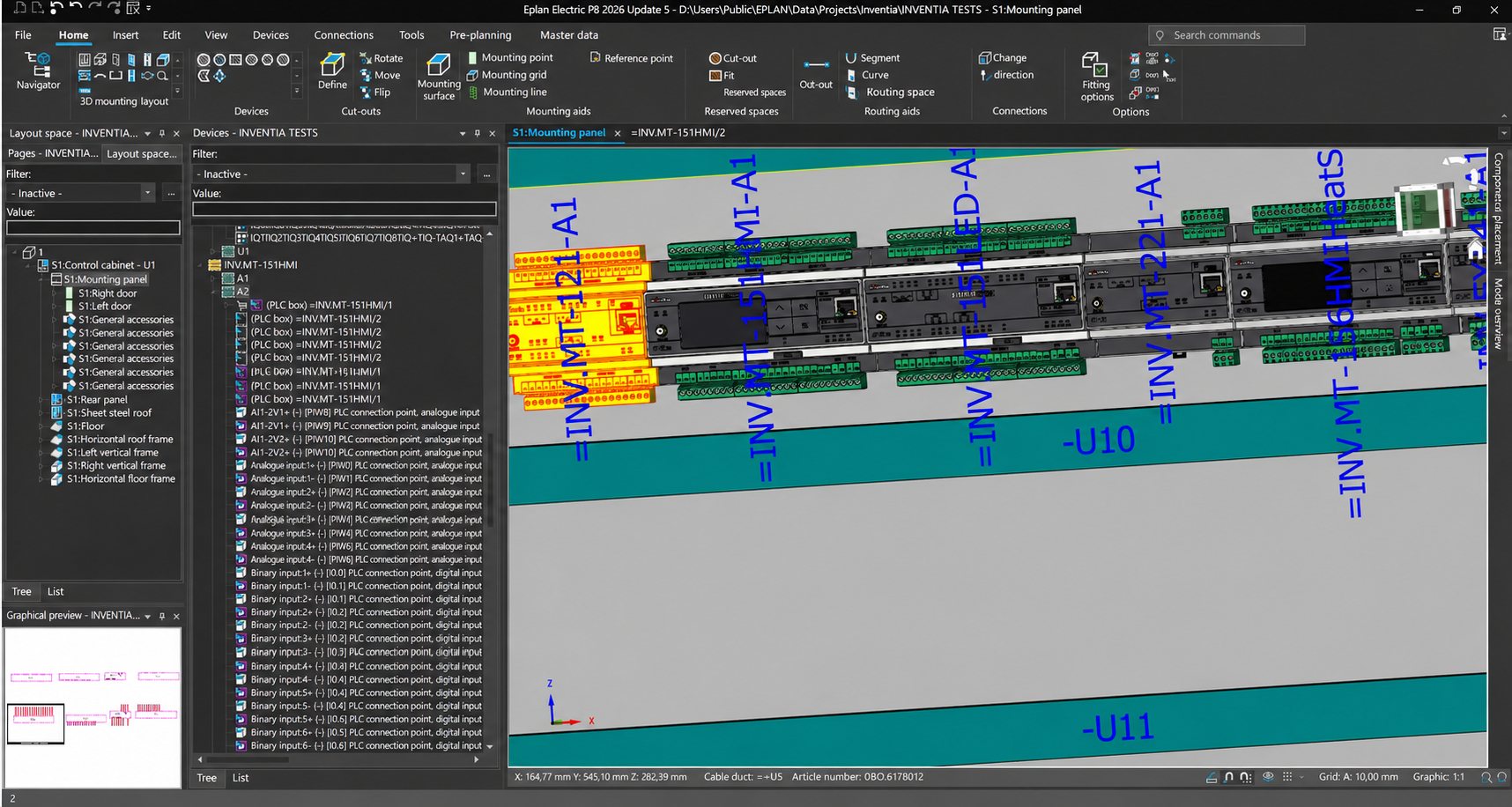
A 3D model allows the module to be incorporated into a spatial layout design. It makes it easier to assess its position relative to the power supply, protective devices, terminal blocks and other equipment. The designer can check in advance whether the chosen layout makes sense and whether it requires any changes to the equipment’s positioning.
This is particularly useful during retrofitting, when a new controller and additional inputs or outputs need to be accommodated within an existing cabinet. The ability to test the layout within the design helps to minimise the number of adjustments required during installation.
The model itself does not replace a check of the installation requirements. Access to connectors, space for cables and maintenance access must still be provided in accordance with the equipment documentation. However, it provides a much better basis for these decisions than a rough rectangle on a drawing.
Less manual data entry, lower risk of errors
Every time the same information is re-entered, there is a potential for error. This could be an incorrect device designation, a mixed-up variant, or a discrepancy between the schematic and the bill of materials.
Using the manufacturer’s data reduces the number of such tasks. It makes it easier to maintain consistent module identification throughout the documentation and provides the team with a common basis for their work.
We have prepared the Inventia library in accordance with the EPLAN Data Standard. This standard organises the structure of component data and supports its use in the design process. For the user, the practical benefit is paramount: the data is ready for use in the EPLAN environment, and the scope of work required to develop a component from scratch is reduced.
Lower cost of documentation preparation
The time spent preparing components, re-entering parameters and checking data forms part of the cost of producing documentation. Using the manufacturer’s library reduces the scope of this work and, consequently, the number of man-hours required to prepare the project. The time saved can be allocated to selecting solutions, verifying connections and refining the details of the installation.
The benefit increases for projects involving multiple similar sites. If the documentation relates to a dozen or so pumping stations or dispersed measurement points, a section of the design developed and checked once using the Inventia module can be used as a basis for subsequent sites. The designer adapts it to the equipment and requirements of the specific installation, rather than recreating the same elements each time.
This approach reduces the workload for each subsequent facility and makes it easier to maintain consistent documentation. For a design office or systems integrator, this means the ability to undertake a greater scope of work with the same team resources. For the client, it offers the opportunity to reduce documentation costs, particularly for projects carried out in series or in phases.
Smoother collaboration with the contractor
The documentation is subsequently passed on to those responsible for procurement, cabinet prefabrication, installation and commissioning. The more clearly the equipment used and its layout are described, the easier it is to move from design to implementation.
Product data supports the creation of bills of materials, whilst the cabinet layout design with 3D models helps convey the equipment layout plan to the contractor. This facilitates coordination even before prefabrication begins – at a stage when changing the position of a device is simpler than moving it within a finished cabinet.
For the client commissioning the installation, this provides a better basis for costing and implementation. For the designer and integrator, it means less time spent explaining details that could have been shown in the documentation beforehand.
A library that is also useful in future projects
Many installations feature similar layouts: a controller, power supply, communication and a set of facility signals. Using a single library makes it easier to develop your own documentation standards and apply them to future projects.
For example, a company designing automation systems for pumping stations can base subsequent projects on a tried-and-tested method of presenting the controller and expanders. The number of signals or the facility’s equipment may change, but there is no need to recreate the device data each time. It is also easier to hand over the project to another team member.
Support begins at the design stage
Making the library available in EPLAN is a continuation of the work we began with the inclusion of Inventia devices in the WebCatalogue for SEE Electrical and SEE Electrical Expert. We want designers to have access to our modules within the tools they use on a daily basis.
For us, this is an important step: a device is no longer just an entry in a catalogue, but also a ready-to-use component in the designer’s toolkit. For customers, the benefit is clear – less time spent preparing data, easier layout planning and more efficient documentation preparation.
We invite you to use the Inventia library on EPLAN Data Portal. Search for the manufacturer ‘Inventia’ or the module reference number and use the available data in your project.
Share this article:



Read more articles:
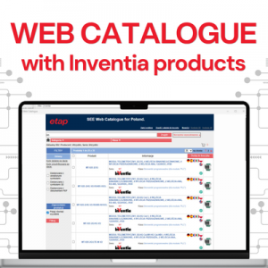
Inventia’s products available in WebCatalogue – easier design with SEE Electrical and SEE Electrical Expert
Check out the latest post and find out more…
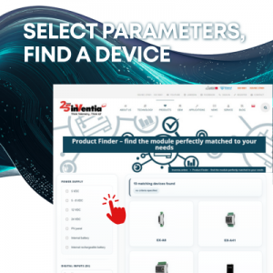
Which telemetry module should you choose? How to select an Inventia device to suit your project’s needs in just a few steps
Discover the product search tool on the Inventia website